Solar rail splices do affect stability and installation outcomes. Properly engineered splices maintain structural integrity and simplify the installation process. These components are not a weakness. They are a necessary part of handling long rail runs and thermal expansion in solar mounting systems.
A quality solar rail splice connector joins rail sections into one continuous beam. An aluminum solar rail splice must handle wind loads and temperature changes without creating failure points. The solar mounting rail connector plays a critical role in overall system performance.
Modern solar mounting designs rely on splices to extend rails across large arrays. Installers follow manufacturer guidelines to achieve safe, efficient results.
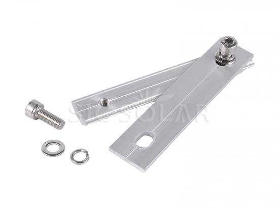
Key Takeaways
-
Solar rail splices connect rail sections to form a strong, continuous beam that handles wind and weather.
-
Proper installation includes correct torque, alignment, and placement to avoid weak points.
-
Splices allow for thermal expansion, preventing buckling in long rail runs.
-
Regular inspections and following manufacturer guidelines ensure long-term stability and safety.
-
Quality splices maintain grounding continuity and protect the entire solar array.
How Solar Rail Splices Affect Stability
Load Distribution and Structural Integrity
A continuous rail ties multiple solar panels together into one unified array. This connection makes the entire structure stronger against wind loads. When wind pushes against a solar panel, the force travels through the panel frame into the solar panel mounting rails. From there, the load moves into the roof structure. A properly joined rail carries this force across the full length of the array. The array acts as a single unit instead of separate pieces.
Modern solar mounting systems distribute weight evenly across roof rafters and trusses. This even spread prevents concentrated stress points that could damage the roof or the mounting structures. Engineers design solar panel mounting rails to transfer loads in a predictable path. Each connection point shares the burden with its neighbors. This shared load path gives the system remarkable structural reliability.
A weak rail splice creates a weak point in this chain. The rail can bend or shift at that joint under heavy wind or snow. A robust solar rail connector ensures the rail behaves as one continuous beam. The splice must match the strength of the rail itself. When it does, the rail performs as if it were a single piece of metal. This behavior maintains structural stability across the whole array.
Potential Failure Points and Mitigation
Every splice is a potential failure point if installers do not treat it with care. The solar rail splice connector must handle tension, compression, and bending forces. These forces change with weather and temperature. A loose connection allows movement between rail sections. That movement can loosen bolts over time. It can also wear down the metal surfaces.
Mitigation starts with proper design. Manufacturers engineer each aluminum solar rail splice to fit specific rail profiles. The splice slides into the rail channel and locks the two sections together. Bolts then tighten the connection to a specified torque value. This process removes play between the sections. A tight joint transfers load without shifting.
Installers must also place splices at the correct locations. A splice near the middle of a span experiences higher bending stress. A splice close to a support point experiences less. Good design places splices where bending moments are lowest. This practice reduces the strain on the solar rail splices.
Thermal expansion adds another challenge. Aluminum expands and contracts as temperature changes. A rail that runs very long needs room to move. In these runs, the rail splice attaches rigidly to only one rail section. The other section can slide slightly. This design prevents buckling and keeps the solar mounting stable.
Regular inspection also matters. Bolts can loosen after years of wind vibration. A quick check during routine maintenance catches small issues before they grow. This simple step protects the investment and extends system life.
Installation Impacts on Mounting Rails
Alignment Challenges and Time Savings
An aluminum solar rail splice demands precise alignment during installation. The splice slides into the channel of two rail sections. Both sections must sit level with each other. Any twist or height difference creates a weak joint. Installers check rail spacing before they tighten any bolts. Correct rail spacing keeps the panels square and the array straight.
The solar rail splice connector also requires proper fastening. Bolts must reach the correct torque value. Too loose, and the joint moves under wind. Too tight, and the metal strips or cracks. Installers use a torque wrench to hit the exact specification. This step takes only seconds per splice. It prevents costly repairs later.
Spacing matters just as much. The rail / fixing spacing determines where splices can sit. A splice placed too close to a support point adds no benefit. A splice placed mid-span faces higher bending stress. Good solar mounting design places splices at low-stress zones. This practice extends the life of the solar rail splices.
SIC SOLAR mounting systems simplify this process. Their designs are simple and durable. Installers save on labor costs because the parts fit together without modification. The solar panel mounting rails from SIC SOLAR reduce guesswork on the job site. A crew can finish a residential roof in less time. That time savings lowers the total installation cost for the homeowner.
Required Tools and Hardware
A typical installation requires a few basic tools. Installers need a torque wrench, a socket set, and a level. A rubber mallet helps seat the splice into the rail channel. Safety glasses and gloves protect against metal burrs. These tools fit in a standard installer's bag.
The solar mounting rail connector often includes pre-assembled hardware. Bolts and nuts come attached to the splice. This design speeds up the installation. The installer slides the splice in place and tightens the bolts. No loose parts fall into the roof gutter or get lost in the grass.
Grounding is another critical step. Rail mounting systems usually indicate that clamps pierce the anodizing. This piercing connects the solar panel mounting rails or frames to the rail. The connection creates a continuous ground path. Proper fastening and routing of ground wires ensures safety. Installers must secure wires to solar panel mounting rails with clips. This step keeps solar panel wiring neat and protected from wind damage.
The rail connector also affects grounding continuity. A metal-to-metal bond across the splice maintains the ground path. Paint or anodizing can block this bond. Installers may need to remove a small patch of coating at the joint. Manufacturer guidelines specify where this step is necessary.
For very long runs, the aluminum solar rail splice attaches rigidly to only one rail. The other rail section can slide slightly. This design allows for thermal expansion. It prevents buckling during hot summer days. This detail matters for solar mounting on large commercial roofs.
Proper installation of mounting rails or frames takes planning. Crews should map splice locations before they start. They mark rail spacing on the roof deck. They pre-drill holes where needed. This preparation avoids delays and keeps the project on schedule. A well-planned installation protects the mounting structures for decades.
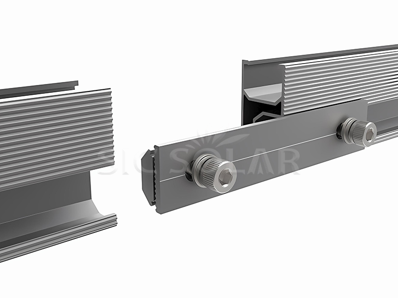
Rail Splice Types for Trapezoidal Metal Roof
Internal vs. External Rail Splices
A solar panel rail splice is designed to be lightweight but durable. It bears the weight of solar panels across long spans. Two main types exist for solar mounting on trapezoidal metal roofs: internal and external connectors. Each type suits different project needs.
| Attribute | Internal Rail Connector | External Rail Connector |
|---|---|---|
| Installation position | Placed inside the aluminum alloy rail | Mounted on the outside of the rail |
| Fastening method | Secured by insertion | Secured with bolts or clamps |
| Exterior appearance | Keeps the rail exterior clean and flush | Adds external protrusions on the rail |
| Structural effect | Enhances connection strength while avoiding external protrusions that could interfere with module installation | Provides accessible external fixing points for easier installation and maintenance |
| Typical application | Large-scale photovoltaic projects requiring fast installation | Certain rooftop photovoltaic applications |
Internal connectors slide inside the rail channel. This design keeps the exterior clean and flush. External connectors bolt to the outside surface. They offer easy access for maintenance. Both types support solar mounting systems for trapezoidal roofs.
Top-Mount vs. Side-Mount Configurations
Different configurations suit various trapezoidal roof solar mounting needs. The L-Foot orientation determines how the rail attaches to the roof structure.
| Rail Configuration | L-Foot Orientation | Installation Step | Stability Implication |
|---|---|---|---|
| Side-mounted rail | Vertical | Orient the L-Foot vertically so the hinge bolt locks into the square hole on the slotted L-Foot, then tighten the hinge bolt. The rail attaches to the remaining slot to fine-tune rail height. | Vertical orientation with hinge bolt locked into the square hole provides a secure, height-adjustable connection for side-mounted rails. |
| Top-mounted rail (or PVKIT) | Horizontal | Orient the L-Foot horizontally, then tighten the hinge bolt. | Horizontal orientation is required for top-mounted rail/PVKIT attachment, ensuring proper alignment and locking. |
In very long runs, a rail splice is rigidly attached to only one rail. This allows for thermal expansion. The other section slides slightly. This detail matters for solar mounting on trapezoidal metal roofs with wide spans. A quality solar rail connector maintains the ground path across the joint. The best solar mounting systems for trapezoidal roofs account for this movement. Proper rail connection design prevents buckling during temperature swings.
Best Practices for Proper Splicing
Step-by-Step Installation Guidelines
Manufacturers design each solar rail splice connector for specific rail profiles. Installers must follow the manufacturer's instructions and international standards like AS/NZS 1170 and JIS 8955:2011. These standards guide structural reliability for solar mounting on trapezoidal metal roofs.
A proper installation follows a clear sequence:
-
Account for thermal expansion at each splice. Aluminum expands and contracts with temperature changes. A 6 m rail can move about 14 mm between -10°C and 70°C.
-
Maintain the specified thermal expansion gap of 6–10 mm between rail section ends at each splice connector.
-
Do not push rail sections together to close the gap before fastening. Some systems use floating splice connectors that let rail ends slide independently.
-
Position the splice according to the manufacturer's maximum splice offset from the nearest support point. This offset is typically no more than 20% of the span length from the attachment point.
-
Torque all splice connector fasteners to the manufacturer's specified values using a calibrated torque wrench. Typical mid-clamp and end-clamp values for aluminum-framed modules are 8–16 N·m. Always verify the module manufacturer's clamping requirements.
Rail splice connectors join aluminum solar rail sections end-to-end using internal or external splice connectors — short aluminum extrusions or cast aluminum blocks inserted into or over the rail ends and secured with fasteners. A properly designed splice connector transfers bending moment across the joint to maintain structural continuity over the rail's full length.
SIC SOLAR operates under a strict ISO9001 quality management system. Their solar mounting systems meet AS/NZS 1170 and JIS 8955:2011 standards. SIC SOLAR offers a 10-year warranty as a benchmark for reliability. For rail extension applications, explore the solar panel mounting rail splice kit.
Common Mistakes to Avoid
Installers sometimes over-torque fasteners. This action can crush panel frames or crack module glass. Under-torquing creates a different problem. Bolts can loosen under cyclic wind loading. Both errors weaken the aluminum solar rail splice and threaten the mounting structures.
Poor alignment is another common error. Rail sections must sit level with each other. Any twist or height difference creates a weak joint. Installers should check rail spacing before tightening bolts. Correct rail spacing keeps the array square and straight.
Placing a splice at mid-span increases bending stress on the joint. Good design places splices at low-stress zones. This practice extends the life of the solar mounting rail connector.
Installers must also maintain grounding continuity. Paint or anodizing can block the metal-to-metal bond across the splice. Manufacturer guidelines specify where to remove a small patch of coating.
Following these best practices ensures secure mounting structures. Proper installation protects the investment and maintains structural reliability for decades.
Solar rail splices are beneficial and safe when used correctly. They are a standard part of professional solar installations. A quality solar rail splice connector maintains structural integrity across long rail runs. Proper design and installation are key to maintaining stability. Installers should follow manufacturer guidelines and best practices for a reliable solar mounting system. The solar mounting rail connector must match the rail profile and handle thermal expansion. An aluminum solar rail splice ensures the array behaves as one continuous beam. These practices protect the investment and ensure solar mounting success for decades.
FAQ
Do solar rail splices weaken a mounting system?
No. A properly engineered solar rail splice connector maintains structural continuity across rail sections. It transfers bending moment and wind loads just like a continuous beam. A weak splice creates a failure point, but a robust aluminum solar rail splice matches the rail's strength and keeps the array stable.
How much thermal expansion gap does a splice need?
Installers should maintain a 6–10 mm gap between rail section ends at each splice connector. Aluminum expands and contracts with temperature changes. A 6 m rail can move about 14 mm between -10°C and 70°C. This gap prevents buckling and keeps the solar mounting rail connector secure.
What torque value should installers use on splice fasteners?
Installers must torque splice connector fasteners to the manufacturer's specified values using a calibrated torque wrench. Typical mid-clamp and end-clamp values for aluminum-framed modules are 8–16 N·m. Always verify the module manufacturer's clamping requirements before tightening. Over-torquing can crush frames, while under-torquing allows bolts to loosen under wind loading.
Where should installers place splices on a rail run?
Installers should position splices at low-stress zones, not mid-span. The maximum splice offset from the nearest support point is typically no more than 20% of the span length. This placement reduces bending stress on the aluminum solar rail splice and extends its service life.
Can a splice maintain grounding continuity?
Yes, when installed correctly. A metal-to-metal bond across the splice maintains the ground path. Paint or anodizing can block this bond, so installers may need to remove a small patch of coating at the joint. Manufacturer guidelines specify where this step is necessary.